Extend your on-premises Layer 2 subnet into AWS, preserving original IP addresses and eliminating application reconfiguration during lift-and-shift migrations.
Overview
This Guidance demonstrates how to extend Layer 2 networks between on-premises data centers and AWS when organizations need seamless connectivity across hybrid environments, using Cisco Catalyst 8000v virtual routers with automated CloudFormation deployment. CloudFormation templates automate the infrastructure provisioning with pre-configured LISP and IPSec settings, eliminating manual setup steps. The LISP protocol separates network identifiers from physical locations, while secure IPSec tunnels transport encapsulated Layer 2 frames between environments, maintaining original addressing throughout the traffic flow. You gain seamless network connectivity across hybrid environments while reducing manual configuration overhead and accelerating deployment time from days to hours.
Benefits
Migrate workloads without re-addressing
Automate complex hybrid network deployment
Deploy pre-configured LISP, IPSec, and OSPF protocols across both environments using AWS CloudFormation, reducing manual setup errors and accelerating time to production.
Secure cross-site traffic end-to-end
Encrypt all data traversing between your data center and AWS through IPSec tunnels while maintaining seamless Layer 2 connectivity for your applications.
How it works
These technical details feature an architecture diagram to illustrate how to effectively build this solution. The architecture diagram shows the key components and their interactions, providing an overview of the architecture's structure and functionality step-by-step.
 Step 1
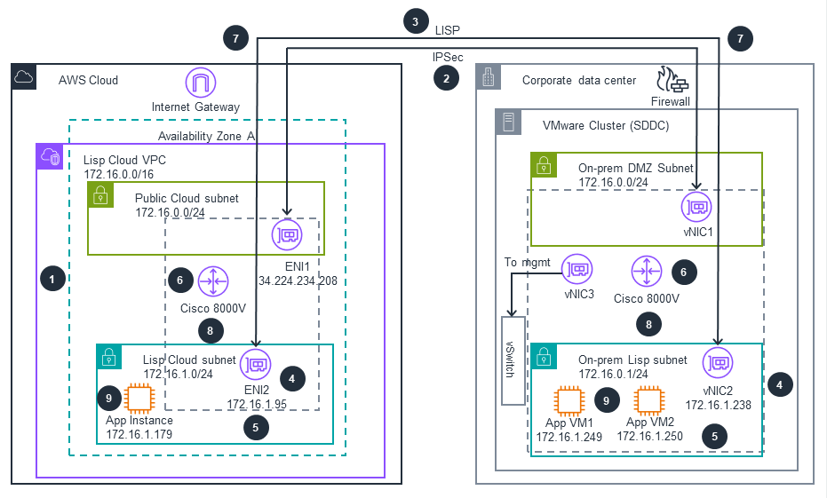
AWS CloudFormation deploys the infrastructure, provisioning both the AWS Cloud and on-premises Cisco Catalyst 8000V routers with pre-configured LISP, IPSec, and OSPF settings.
Step 2
A secure IPSec tunnel is established between the on-premises Cisco Catalyst 8000V via Virtual Network Interface Card 1 (vNIC1) and the AWS Cisco Catalyst 8000V via Elastic Network Interface1 (ENI1) through the AWS Internet Gateway.
Step 3
The LISP protocol initializes on both routers, separating endpoint identifiers (EIDs) from routing locators (RLOCs) to enable Layer 2 network extension.
Step 4
Secondary IP addresses are configured on router interfaces, Elastic Network Interface2 (ENI2) on the AWS side. vNIC2 on-prem learns hosts directly through ARP broadcasts. This activate the Layer 2 extension capability.
Step 5
Traffic originates from either environment, whether from on-premises application virtual machines (App VM1: 172.16.1.249, App VM2: 172.16.1.250) or from the AWS Cloud (App Instance: 172.16.1.179).
Step 6
The Cisco Catalyst 8000V (either on-premises or in AWS Cloud) encapsulates Layer 2 frames with LISP headers to enable transport across Layer 3 networks.
Step 7
The encapsulated traffic is encrypted using IPSec and transmitted through the secure tunnel via the AWS Internet Gateway on the AWS Cloud side and Firewall on the Corporate data center
Step 8
The destination Cisco Catalyst 8000V (either in AWS Cloud or on-premises) decrypts and decapsulates the traffic, then routes it to the appropriate subnet via ENI2 or vNIC2.
Step 9
The packets reach their destination application, maintaining the original Layer 2 addressing throughout the entire flow regardless of traffic direction.
Deploy with confidence
Everything you need to launch this Guidance in your account is right here.
We'll walk you through it
Dive deep into the implementation guide for additional customization options and service configurations to tailor to your specific needs.
Let's make it happen
Ready to deploy? Review the sample code on GitHub for detailed deployment instructions to deploy as-is or customize to fit your needs.